
Heliformed dead end clamp
The equipment covered in this catalogue section should be installed,used,and serviced by professional person who very familiar with this products. This equipment is for use by above person and is not intended as a substitute for adequate training and experience in safe procedures for this type of equipment. This catalog information do not cover all details or situations in equipment use,or they provide for every possible contingency to be encountered in relation to installation,operation or maintenance,it should additional information and details be desired,or if specific situations arise which are not covered adequately for the user’s purpose,the specifics should be referred to Laurence Electric Power Equipment Co.,LTD.
The Heliformed Line Fittings was including:
Armor Rods are recommended as minimum protection for clamp-type supports or suspensions.
Line Guards are recommended as minimum protection for hand-tied spans.The use of supplementary damping devices,such as Spiral Vibration Dampers,should be considered when conductor vibration is present or expected.
Heliformed Ties are recommended as being superior to armor-hand tie combinations in providing pr otection from abrasion,and equivalent in providing protection from vibration fatigue.
Suspension clamp is recommended as being superior to armorclamp combinations in providing protection from benging stress,compression stress and abrasion.
Repair Armor Rods.Armor Rods may be used to restore full conductance and strength to ACSR and aluminum conductors where damage does not exceed approximately 50 percent of the outer strand layer,Consult Factory for repair capability of specific standings.
NOTE:When Armor Rods are used to repair damaged aluminum-based conductors,the fo llowing ap plication steps are required for optimum
electrical repair:
Step 1: Thoroughly wire-brush damaged conductor for the full length of the Armor Rods to be applied.
Step 2:Apply a gritted inhibitor to the full length of this area before applying the Armor Rods.
Tapping.
Tapping over applied aluminum Armor Rods is permissible. Where it is known that tapping clamps will be installed over Armor Rods, it is recommended that the conductor be thoroughly wire brushed clean,and then and inhibitor is applied.
Inspection.
After application of the correct number of rods per set,a slight gap between rods sho uld be pr esent. Co nsult the General Information Section for detailed explanation.

Heliformed dead-ends,manufactured of aluminum covered steel or galvanized steel,is designed for single-pole distribution construction.
Mechanical strength meets the requirements of primaries, secondaries,and substation feeders.
Heliformed dead-end is recommended for direct application over plastic jacketed(not fabric covered) conductor.
Coated dead-ends are also recommended for jacketed conductor.The Heliformed dead-ends is designed to grip the conductor uniformly to prevent distortion of the conductor.It also offers a unique design that eliminates bolts, nuts,wash ers and ot her comp onent parts t hat may be come lost or damaged during installation or in service.
During installation,and at all times,care should be taken to avoid gouging or damaging the coa ting of th e Heliformed dead-end or the conductor itself.Heliformed dead-ends should not be used as tools;for example come-alongs, puling-in grips,etc.Tools are not required nor recommended to install Heliformed dead-ends, except for hot stick applications.
Safety Considerations
1.This product is intended for a single (one-time) use and for the specified application
2.This product is intended for use by trained craftspeople only. This product should not be used by anyone who is not familiar with and trained in the use of it.
3.When working in the area of energized lines with this product,extra care should be taken to prevent accidental electrical contact.
4.For proper performance and personal safety be sure to select the proper size with preformed Armor Rods and clamps according the conductors size before application.
5.Dead ends are precision devices.To insure proper performance,they should be stored in cartons under cover and handled carefully.
6.The Dead ends are simple installation,except the need the screwdriver to seperated the conductor ends ,usually needn’t a ny other tools,just install by hand.
The over head Dead ends have been designed as a simple and cost effective method of carrying out terminations on overhead distribution networks incorporating AAC,/AAAC and ACSR Conductors.Also it have was used for 1kV and 10kV insulated conductors.Their unique single piece design, provides u niform application pressure to the conductor,and eliminates cumbersome hardwa re and other components,which may be l ost or dam aged during installation or in service.An entire range of fittings,have been developed,to cover the smallest earth wires,right up to the largest transmission conductors.Each fitting has a specific application range,as indicated in the flollowing tables.
Dead ends:Aluminum covered steel or galvanized steel
Thimble:iron hot dip galvanized
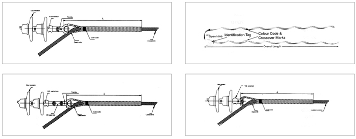
Open looped:It was suit for small size conductors.
Cable looped:It was suitable for big size conductors.
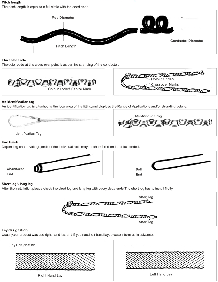
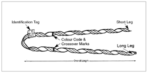
Crossover Marks:Indicate starting point for application on conductor.
Color Corde and Length:Assist in identification of conductor diameter range.
Identificaton Tag:Identifies conductor type,and diameter range.
| Cross section (mm2) |
Conductor diameter | Length | Pieces | |
| Min.(mm) | Max.(mm) | |||
| LNL-16/3 | 16/3 | 5.55 | 444 | 3 |
| LNL-25/4 | 25/4 | 6.96 | 546 | 3 |
| LNL-35/6 | 35/6 | 8.16 | 622 | 3 |
| LNL-50/8 | 50/8 | 9.60 | 685 | 3 |
| LNL-70/10 | 70/10 | 11.4 | 736 | 3 |
| LNL-95/15 | 95/15 | 13.61 | 876 | 4 |
| LNL-95/20 | 95/20 | 13.87 | 876 | 4 |
| LNL-120/7 | 120/7 | 14.5 | 876 | 4 |
| LNL-120/20 | 120/20 | 15.07 | 889 | 4 |
| LNL-120/25 | 120/25 | 15.74 | 889 | 4 |
| LNL-150/8 | 150/8 | 16.00 | 889 | 4 |
| LNL-150-20 | 150/20 | 16.67 | 1016 | 5 |
| LNL-150/25 | 150/25 | 17.10 | 1016 | 5 |
| LNL-150/35 | 150/35 | 17.5 | 1016 | 5 |
| LNL-185/10 | 185/10 | 18.00 | 1016 | 5 |
| LNL-185/25 | 185/25 | 18.88 | 1155 | 6 |
| LNL-185/30 | 185/30 | 18.90 | 1155 | 6 |
| LNL-185/45 | 185/45 | 19.00 | 1155 | 6 |
| LNL-210/10 | 210/10 | 19.60 | 1155 | 6 |
| LNL-210/25 | 210/25 | 19.98 | 1155 | 6 |
| LNL-210/35 | 210/35 | 20.38 | 1155 | 6 |
| LNL-210/50 | 210/50 | 20.86 | 1155 | 6 |
| LNL-240/30 | 240/30 | 21.60 | 1270 | 8 |
| LNL-240/40 | 240/40 | 21.66 | 1270 | 8 |
| LNL-300/15 | 300/15 | 23.04 | 1270 | 8 |
| LNL-300/20 | 300/20 | 23.43 | 1270 | 8 |
| LNL-300/25 | 300/25 | 23.76 | 1442 | 10 |
| LNL-300/40 | 300/40 | 26.94 | 1442 | 10 |
| LNL-300/50 | 300/50 | 24.26 | 1442 | 10 |
For 10KV insulated conductor
| Cross section (mm2) |
10kV conductor GB/14049-93 JKLYJ | Length | |
| Section(mm2) | O.D(mm) | ||
| LNL-10-35/JY | 35 | 14.8 | 890 |
| LNL-10-50/JY | 50 | 16.10 | 890 |
| LNL-10-70/JY | 70 | 17.80 | 980 |
| LNL-10-95/JY | 95 | 19.60 | 1016 |
| LNL-10-120/JY | 120 | 21.00 | 1016 |
| LNL-10-150/JY | 150 | 22.60 | 1016 |
| LNL-10-185/JY | 185 | 24.20 | 1016 |
| LNL-10-240/JY | 240 | 26.40 | 1016 |
For AAC conductor
| Cross section (mm2) |
conductor LJ GB/T1179-1983 | Length | color code | |
| Section(mm2) | O.D(mm) | |||
| LNL-16/LJ | 16 | 4.62-5.16 | 406 | blue |
| LNL-25/LJ | 25 | 5.8-6.53 | 444 | orang |
| LNL-35/LJ | 35 | 7.35-8.26 | 622 | red |
| LNL-50/LJ | 50 | 8.27-9.25 | 685 | green |
| LNL-70/LJ | 70 | 10.4-11.25 | 736 | blue |
| LNL-95/LJ | 95 | 11.69-13.11 | 800 | orange |
| LNL-120/LJ | 120 | 13.12-14.66 | 876 | red |
| LNL-150/LJ | 150 | 14.67-16.59 | 889 | black |
| LNL-185/LJ | 185 | 16.6-18.77 | 1016 | green |
| LNL-210/LJ | 210 | 16.6-18.77 | 1016 | green |
| LNL-240/LJ | 240 | 18.78-21.26 | 1155 | orange |
| LNL-300/LJ | 300 | 21.27-24.05 | 1270 | blue |
| LNL-400/LJ | 400 | 24.06-27.2 | 1422 | brown |
| LNL-500/LJ | 500 | 27.21-30.78 | 1651 | orange |
For AS conductor
| Cross section (mm2) |
conductor LJ GB/T1179-1983 | Length | color code | |
| Section(mm2) | O.D(mm) | |||
| LNL-25/G | 25 | 6.6 | 635 | yellow |
| LNL-35/G | 35 | 7.65-7.95 | 711 | black |
| LNL-50/G | 50 | 8.95-9.30 | 901 | orange |
| LNL-70/G | 70 | 10.82-11.10 | 1016 | green |
| LNL-95/G | 95 | 12.5 | 1333 | orange |
| LNL-100/G | 100 | 13 | 1333 | yellow |
| LNL-120/G | 120 | 14 | 1460 | yellow |

